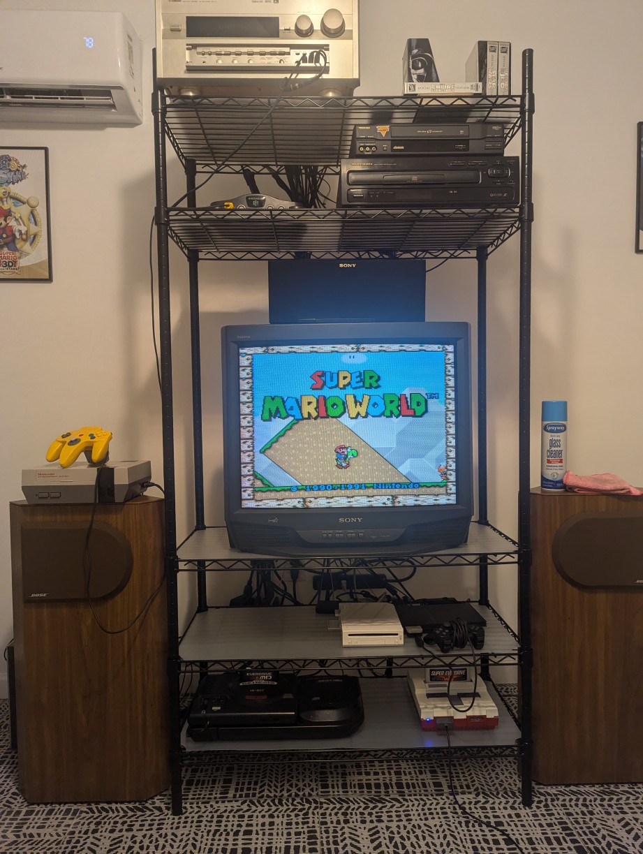
I’ve always been a CRT purist when it comes to retro gaming, and I’ve held onto my family’s Sony WEGA Trinitron since the early 2000s for that purpose. Eventually, though, I got frustrated by the geometry issues that the flat-screen Trinitrons face (bowing of horizontal lines on those models is common), and wanted to try one of the more sought after late 90s curved-screen models. What had always held me back is my obsession with using the best quality video connections with my retro systems. The curved-screen models tend to top out at S-Video, rather than YPbPr component, which is what I use with my PS2, Xbox, and Wii systems.
I had heard in recent years of people performing RGB mods on popular CRTs like these Trinitrons. RGB SCART is a connection that is equivalent to component that is supported natively by my many retro systems — the connection was popular in Japan and Europe — but almost no TVs or monitors in the US supported it. It’s become a holy grail of video quality for many retro systems. Downstream of that are component video mods, which can generally be installed side-by-side with RGB mods, so I decided to try adding both to a Sony KV-27S66 I managed to track down on Marketplace.
To take a step back, most people used RF or composite video (the yellow, white, red cables) on their retro systems back in the day. Composite video carries all of the video information in a single wire, which makes for a blurry or smeared image since the luma and chroma signals interfere with each other. S-Video, which provides a much sharper image, carries luma and chroma via separate pins, which is an improvement. RGB carries all of the color signals separately, which provides both a sharp and vibrant image (component works similarly, the green cable is actually the luma signal and the red and blue are phase shift signals — the green color is then derived from those).
Luckily, these mods are well-documented and have resources available online, for example on the CRT Database and Sunthar’s Super Sector. The basic idea is pretty clever. The on-screen display for most of these TVs (which displays the menu, or the volume bar, channel number, etc) is actually drawn using RGB signals. When you press volume up, for example, the screen goes blank, the volume bar is drawn, and then the program or game returns. This happens quickly enough that, to us, the volume bar appears on top of the program. The idea of this mod is to trick the TV’s chip, by telling it to always keep the screen “blank” and then inject the RGB signals that we’d like to display, which in this case, is the video feed from the retro system. The component mod functions similarly, except the signals are injected into the picture-in-picture circuit which uses the same video format as component.
I also decided to recap the unit while I had it open — since it couldn’t hurt as preventative maintenance and caps are cheap these days. This led to an issue: when I got it recapped and back together, the unit wouldn’t turn on. When I removed the back, it popped to life. Unfortunately, in the process of recapping, I had cracked the board in a pretty integral spot.
By flexing the board up and down, I was able to see the symptoms of that crack. What was really unfortunate is the location — it had cracked across about 20 or so traces that run all the way from one side of the board to the other. I had to meticulously scrape away the coating of the board, trace the continuity to one end and the continuity to the other, and then connect those points with a wire to correct where they had become disconnected on the board. This is a very tedious and time consuming task, though not overly difficult. The problem is really the sheer number of connections that had to be redone. There were a few knock on effects as well — the amplifier IC for the internal speakers had blown and needed replaced for example — but I ultimately got functionality restored.
I spent a lot of time after that dialing the geometry in, fixing it to my liking using neodymium magnets placed on the deflection yoke. I also repositioned the yoke to correct some tilt issues, redid the adhesive on the little rubber blocks used to hold it in place, and color calibrated to D93). It’s not perfect, but you’d be hard-pressed to find a better looking 27″ CRT in 2024 than this one! It ended up being a much more involved project than I originally anticipated, but I’m very happy with the result! So far, I’ve played through Star Fox, Super Metroid, Link to the Past, and most of the games on Mario All-Stars. My next step is likely going to be RGB modding my NES, which did not have native RGB output, and playing through some games on there as well.


